PLC Communication protocols analysis is a critical aspect of understanding how Programmable Logic Controllers (PLCs) within automated systems.
However, any disruption or misconfiguration can lead to severe consequences, including operational downtime and equipment damage. In this article, I will delve into a detailed analysis of the MicroLogix 1400’s communication protocols using Wireshark. By examining real-life packet data and outlining the steps involved in program sub-routine.
I aim to shed light on the crucial aspects of PLC communication and highlight how vulnerabilities can be identified and mitigated. Understanding these protocols is vital for maintaining the reliability and security of these systems.
If you are not sure how to get these communication protocol packets.
Please refer to Phase 2: MitM Attack
MicroLogix 1400: A Critical Component at Risk
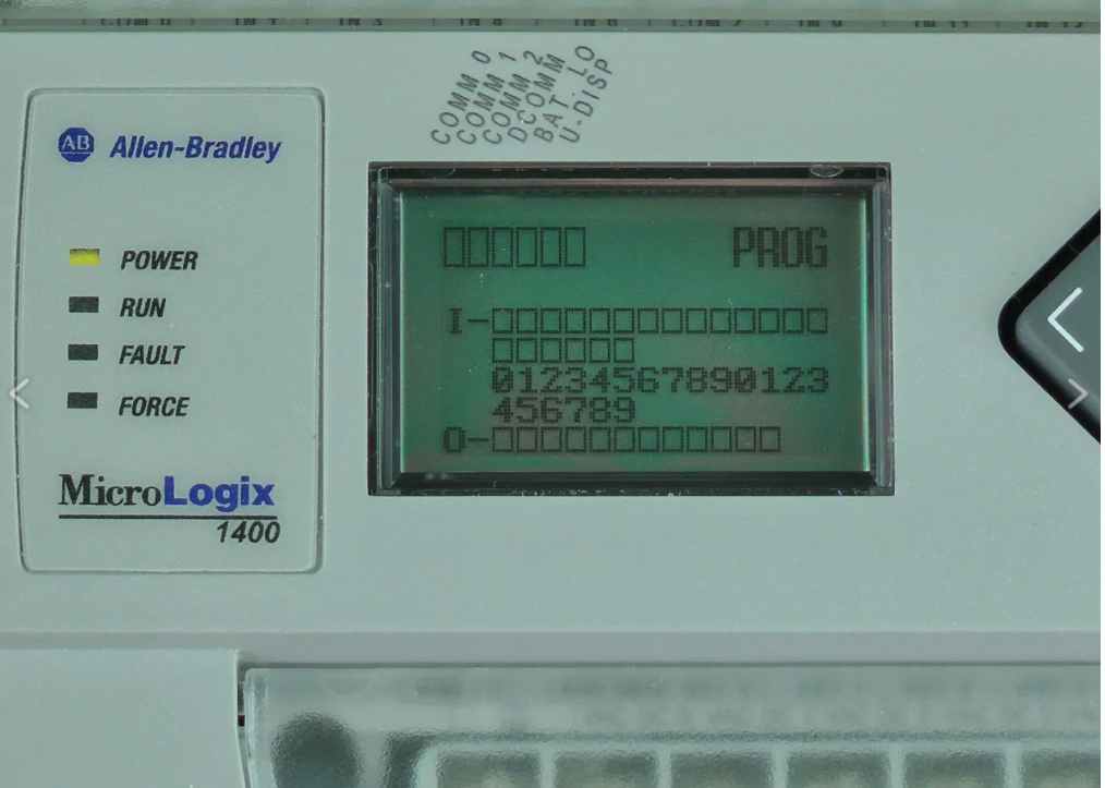
The MicroLogix 1400 PLC from Rockwell Automation’s Allen-Bradley is engineered for crucial roles in industries like printing, food and beverage processing, and wastewater treatment. Equipped with an onboard I/O module, a built-in LCD display, and remote configuration capabilities, this PLC is a key player in maintaining the smooth operation of complex processes.
However, its importance cannot be overstated. If the MicroLogix 1400 is forced offline or its configuration is tampered with, the consequences can be severe. Such disruptions can halt critical operations, leading to significant service interruptions or even catastrophic damage to equipment. The stakes are high—protecting the integrity and operation of the MicroLogix 1400 is essential to preventing potentially devastating impacts on your system.
Objective:
The objective of this PLC Communication protocols analysis is to thoroughly understand and document the process of downloading a ladder logic program to a PLC. This involves capturing and analyzing the entire communication sequence, including the TCP handshake, register session establishment, and program download routine. By examining packet exchanges and interactions, the goal is to validate the remote connection and ensure that all requests are correctly processed by the PLC.
Communications Protocol:
Communicating with the MicroLogix 1400 involves configuring and controlling the device via its serial or Ethernet interfaces. The Allen-Bradley DF1 protocol is typically used for serial communication. For Ethernet connectivity, the most prevalent protocol is EtherNet/IP (ENIP). ENIP is a TCP-based implementation of the Common Industrial Protocol (CIP), widely used in Allen-Bradley products.
EtherNet/IP supports various methods of data transmission, with the two primary types being Connected and Unconnected Messages. The details of ENIP are publicly documented in the “Communicating with RA Products using EtherNet/IP Explicit Messaging” and “EtherNet/IP Adaptation of CIP” guides.
PCCC (Programmable Controller Communication Commands) are application-layer instructions sent to the PLC using either DF1 or ENIP protocols. These commands follow a structured format that includes command and function code pairs, along with any necessary data to execute specific logical operations on the device. Comprehensive details on the command structure are available in the “Allen-Bradley DF1 Protocol and Command Set” document.
Understanding these communication methods is crucial for ensuring reliable interactions with the MicroLogix 1400 and mitigating risks associated with potential disruptions.
Over-Taking the MicroLogix 1400
During my research, I uncovered multiple vulnerabilities in the MicroLogix 1400 that can be exploited by a malicious actor to remotely configure, control, modify, and even disable the device. By exploiting these vulnerabilities and utilizing both documented and undocumented functionalities, I was able to take control of a target device running the latest firmware available at the time.
PLC Communication Protocol Analysis:
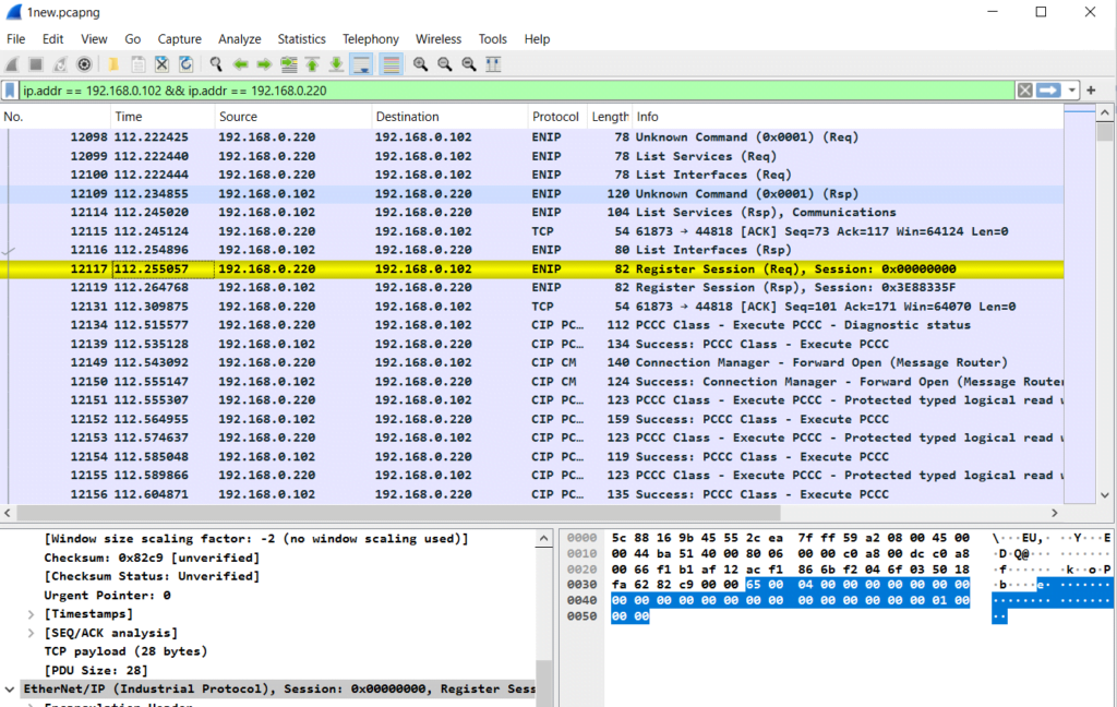
The first step in my protocol analysis was to write and download a new ladder logic program to the PLC memory. This allowed me to start capturing the communication from the very beginning. It all began with the initial TCP handshake. After that, a registered session was created.
program routine:
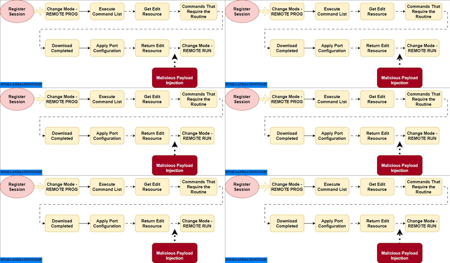
Register_Session()– After this step , Next, I identified the program routine used for downloading the ladder logic program into the PLC memory, which includes…”
-
- STEP1. Change Mode – REMOTE PROG
- STEP2. Execute Command List
- STEP3. Get Edit Resource
- STEP4. Any Commands That Require the Routine (This step will be discuss in details in phase 4[DPI])
- STEP5. Download Completed
- STEP6. Apply Port Configuration
- STEP7. Return Edit Resource
- STEP8. Change Mode – REMOTE RUN (optional)
1. Register_Session()
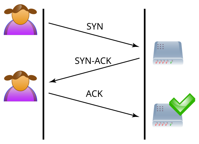
beginning with the initial TCP handshake.
PLC:
IP Address: 192.168.0.102
Subnet Mask: 255.255.255.0
Default Gateway: 192.168.0.1
SCADA System:
IP Address: 192.168.0.220
Subnet Mask: 255.255.255.0
Default Gateway: 192.168.0.1
Ghost PC (Attacker’s Machine):
IP Address: 192.168.0.44
Subnet Mask: 255.255.255.0
Default Gateway: 192.168.0.1
Next, a register data is sent to the PLC. If the register data is correct, the PLC responds with a register handle. After that, a registered session is created

STEP1. Change_CPU_mode(REMOTE_PROG)
To successfully complete the programming routine, the device must be in remote key switch mode. This means we need to set the PLC to remote program mode before making any changes to its memory module.
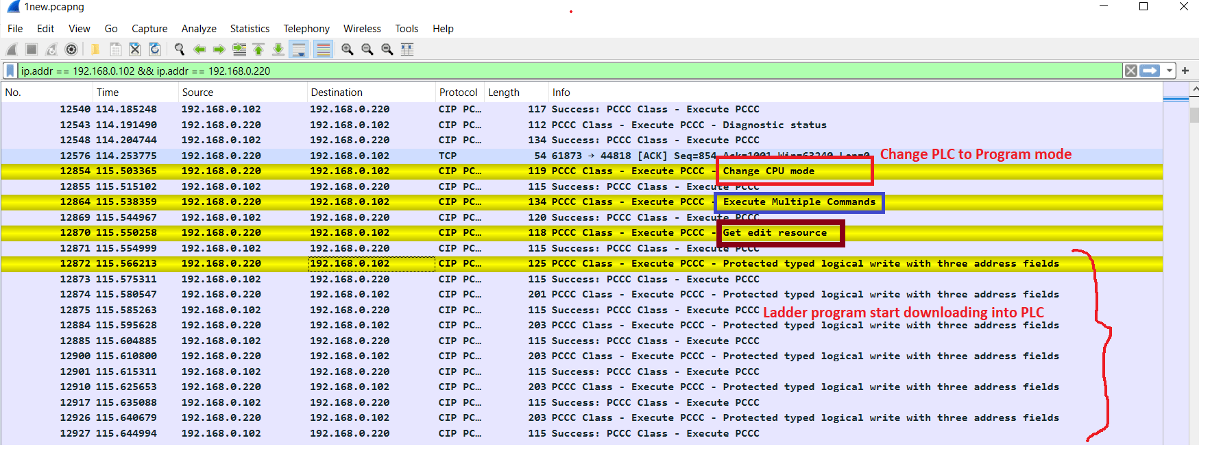
After this CPU mode change ,
STEP2: Execute_multiple_command()
STEP3: Get_edit_resource()
should be executed to initiate a “Programming Routine”.
After getting edit resources the ladder logic program is start downloading to plc memory. As you can see in above picture that there is several wire packet is being send to plc.
Once first three setup commands (1,2&3) have been successfully executed, the desired commands can be run. There does not appear to be any limit on the number of commands sent as long as they are all within the same session.
STEP4: Any Commands That Require the Routine()
Actually this step is used to change to value of status register which include Force Enable & Force Installed functionality and many more.
I will carryout a packet analysis for this in upcoming Phase 4.
STEP5: Download_completed()

This Packet is send to PLC mentioning that all the data packet has been successfully transferred to PLC.
STEP6: Apply_port_configuration()
&
STEP7: Return_edit_resources()
After returning this edit resource, our PLC is now in a condition to accept any PCCC command write operation. We can write as much as register before changing the CPU mode REMOTE RUN mode.

STEP8: Change_CPU_mode(RUN)
This step is used to put back PLC in its original state. After making this RUN mode , all the changes we made in pervious steps are going to Apply. And our PLC will work with modified value.
Conclusion
each packet involved in the process will be analyzed in detail during Phase 4: Deep Packet Inspection (DPI). This phase will provide a comprehensive examination of the packet contents, ensuring a thorough understanding of the communication protocol and any potential vulnerabilities
<—Prev
Phase # 2: MitM
Next —->
Phase # 4 : DPI of PLC
